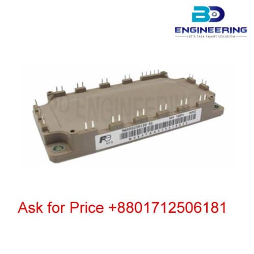

FUJI IGBT Module 7MBR25SA120-60 1200V/25A Inverter-VFD-Ac Servo Drive in Dhaka-BD. It is most of important parts for repair Inverter-VFD. How to find out IGBT Faults in the VFD Control circuit? Why we can use IGBT in inverter-VFD?
Which is convert to DC to Alternative Current. The IGBT’s supply to AC current from the DC bus which is swithcing by gate drive. The IGBT is used in medium to high–strength packages. like switched-mode power materials, traction motor control and induction heating. it makes DC to AC in the Inverting circuit.
Technical Specification:
| Description | Symbols | Conditions | Maximum | |||
|
Inverter
|
Collector-Emitter voltage | VCES | GOOD | 1200 | ||
| Gate-Emitter voltage | VGES | GOOD | ±20 | |||
|
Collector current
|
IC | Continuous | TC=100°C | 25 | ||
| Icp | 1ms | TC=80°C | 50 | |||
| -IC | 25 | |||||
| -Ic pulse | 1ms | 50 | ||||
| Collector power dissipation | PC | 1 device | 170 | |||
|
Brake
|
Collector-Emitter voltage | VCES | 1200 | |||
| Gate-Emitter voltage | VGES | ±20 | ||||
|
Collector current
|
IC | Continuous | TC=80°C | 25 | ||
| ICP | 1ms | TC=80°C | 50 | |||
| Collector power dissipation | PC | 1 device | 170 | |||
| Repetitive peak reverse voltage (Diode) | VRRM | 1200 | ||||
|
Converter
|
Repetitive peak reverse voltage | VRRM | 1600 | |||
| Average output current | IO | 50Hz/60Hz, sine wave | 25 | |||
| Surge current (Non-Repetitive) | IFSM |
10ms, Tj=150°C
half sine wave |
155 | |||
| I2t (Non-Repetitive) | I2t | 120 | ||||
|
Junction temperature
|
Tj
|
Inverter, Brake | 175 | |||
| Converter | 150 | |||||
|
Operating junction temperature (under switching conditions)
|
Tjop
|
Inverter, Brake | 150 | |||
| Converter | 150 | |||||
| Case temperature | Tc | 125 | ||||
| Storage temperature | Tstg | -40~+125 | ||||
| Isolation voltage | between terminal | Viso | AC-1 min | 2500 | ||
| Screw torque | Mounting | – | M5 | 3.5 | ||