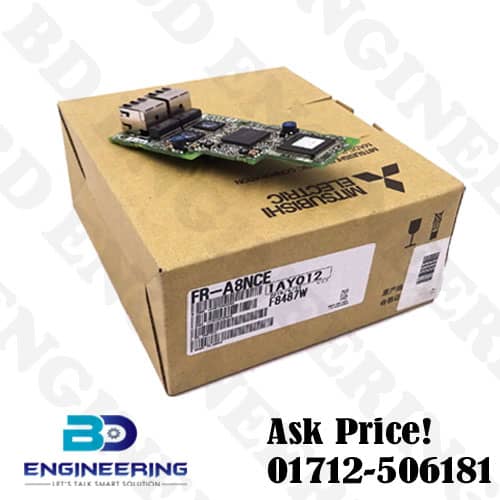
Mitsubishi FR-A8NCE Communication Module price in bd? FR-A8NCE Mitsubishi Electric CC-Link Communication Module Plug-in type. Take the product out of the package, check the product name, and confirm that the product is as you ordered and intact. This product is a plug-in option made for the FR-A800/F800 series.
Symbol | Name | Description | Refer to page |
a | Mounting hole | Used to fix this product to the inverter by inserting a mounting screw or a spacer. | 12 |
b | Connector for communication (PORT 1) | For an Ethernet cable that connects to the network. | 18 |
c | Connector for communication (PORT 2) | For an Ethernet cable that connects to the network. | 18 |
d | Operation status indication LED | Indicates operation/communication status of the inverter by turning ON or blinking. | 8 |
e | Board mounted option connector | Used to connect this product to the option connector on the inverter. | 12 |
More About Mitsubishi Communication Module Specification
Item | Description | |||
Type | Inverter plug-in option type, RJ-45 connector connection method | |||
Power supply | Supplied from the inverter | |||
Transmission speed | 1 Gbps | |||
Communication method | Token passing | |||
Number of units connected | 120 units max. (64 units when all stations are inverters handling 128-word transmissions.) Different devices can be connected together. | |||
Maximum distance between nodes | 100 m | |||
Maximum number of branches | No upper limit within the same Ethernet system | |||
Topology | Line, star, ring, or a combination of line and star | |||
Connection cable | Ethernet cable (IEEE 802.3 1000BASE-T compliant cable or ANSI/TIA/EIA-568-B (Category 5e) compliant shielded 4-pair branched cable) |
|||
Connector | Shielded RJ-45 | |||
Node type
|
Intelligent device station
|
Maximum cyclic size (of one node)
|
RX | 64 bits |
RY | 64 bits | |||
RWr | 128 words | |||
RWw | 128 words |
Mitsubishi FR-A8NCE Communication Module price in bd
Installing the communication option LED display cover. Remove the inverter front (Refer to Chapter 2 of the Instruction Manual (Detailed) of the inverter for instructions for removing the front cover.)Follow instructions for mounting the communication option LED display cover to the inverter front cover. Cut off the tabs on the rear of the inverter front cover with nipper, and remove the separate part to make space for fitting the LED display cover. Fit the communication option LED display cover to the front side of the front Align the LED display cover with the LED position on the circuit board of the option. Push the LED display cover until it is fixed with the clips. Communication option LED display cover
Our Other Product
Yaskawa L1000A Elevator (Lift) Inverter CIMR-LB4A0024FAB 11KW 3 Phase 380-480VAC
Danfoss VLT Micro Drive 0.37KW Inverter
SIEMENS PLC 0CB20 PLC Programming pc Adapter
Weidmuller 8708660000 UL Listed Fire Protected Power Supply
BEIJER Touch Panel EXTER T150 06050B 15inch Graphic HMI
COMPACT CPU 313C WITH MPI 24DI/16DO 4AI 2AO 1PT100 6ES7313-5BE00-0AB0
Siemens Sinamics V90 Servo Drive 0.4KW 6SL3210-5FE10-4UA0 Input 380-480V
Siemens Simatic S7 300 CPU314C-2 PTP 6ES7314-6BH04-0AB0 PLC IN BD
Siemens Simatic S7 300 CPU314C-2DP PLC 6ES7 314-6CH04-0AB0 Price
Siemens S7-1500 CPU1511-1PN Central Processing Unit 6ES7511-1AK02-0AB0