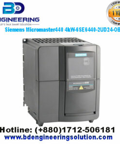
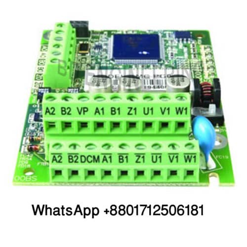
Inverter-VFD PG card for Interface-communication to PLC-Encoder
To integrate a Variable Frequency Drive (VFD) with a PLC and an encoder using a PG (Pulse Generator) card for interface communication, you need to consider several aspects. Here’s a guide on the general setup, common components, and the typical workflow for such an integration:
Components and Considerations
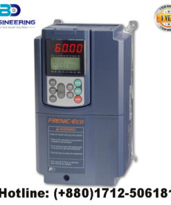
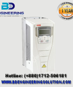
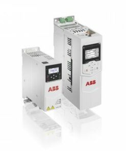
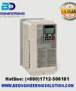
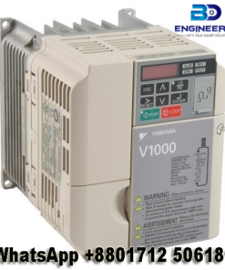
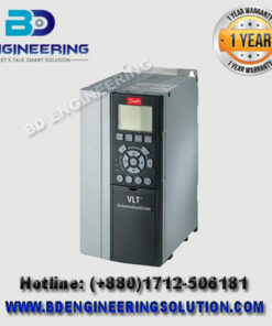
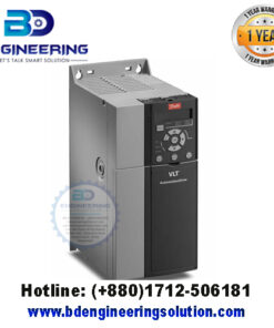
- Variable Frequency Drive (VFD):
- The VFD controls the motor speed and torque by varying the input frequency and voltage.
- It should have a compatible PG card slot for encoder feedback.
- PG Card (Pulse Generator Card):
- The encoder and provides feedback to the VFD for precise speed and position control.
- Common PG cards include models from Mitsubishi, Siemens, Yaskawa, and others, each compatible with specific VFD models.
- Encoder:
- Provides real-time feedback on the motor’s position, speed, and direction.
- Types include incremental and absolute encoders, with incremental being the most common for VFD applications.
- PLC (Programmable Logic Controller):
- Acts as the central control unit for automation, processing inputs, and controlling outputs.
- It needs to communicate with both the VFD and the encoder, often using protocols like Modbus, Profibus, Profinet, or Ethernet/IP.
Workflow for Integration
- Select Compatible Components:
- Ensure the VFD, PG card, encoder, and PLC are compatible with each other.
- Install the PG Card in the VFD:
- Power off the VFD before installation.
- Follow the manufacturer’s instructions to insert the PG card into the designated slot.
- Connect the Encoder to the PG Card:
- Use appropriate cabling to connect the encoder’s output to the PG card inputs.
- Ensure correct wiring for connections as per the encoder and PG card specifications.
- Connect the VFD to the PLC:
- Use the appropriate communication interface to connect the VFD to the PLC.
- Configure the communication settings on both the PLC and the VFD to ensure proper data exchange.
- Configure the PLC:
- Set up the PLC to read the encoder feedback from the PG card via the VFD.
- Program the PLC to control the VFD based on the encoder feedback, implementing necessary logic for speed, position, and torque control.
- Parameter Settings in VFD:
- The VFD parameters to accept the PG card inputs and utilize encoder feedback for control.
- Detailed parameter settings specific to the PG card and encoder integration.
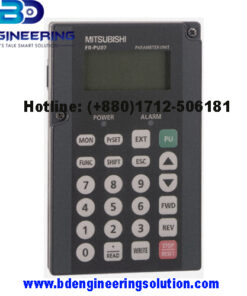
Mitsubishi FR-A700 VFD with FR-A7AP PG Card:
- Components:
- VFD: Mitsubishi FR-A700
- PG Card: Mitsubishi FR-A7AP
- Encoder: Incremental Encoder
- PLC: Mitsubishi FX or Q Series
- Installation:
- Install the FR-A7AP PG card into the FR-A700 VFD.
- Connect the incremental encoder to the PG card using shielded cables.
- Connect the VFD to the PLC using RS485 for Modbus communication.
- Programming:
- Write the PLC program to read the encoder data via the VFD and implement control logic.
- Test the system and make necessary adjustments to ensure accurate control.