TROUBLESHOOTING CONTROL LOOP, How to do it?
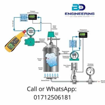
TROUBLE SHOOTING Control Loop Analog 4-20MA. When we verbalize about a good process. we mean an installation in which the input component is able to process as a semi final or final product in a controlled and automate process. In most cases, some supervision and control can exercise in a house. and other buildings where physical production occurs.
The control system activity in industrial processes can predict in 420mA loops which form a common analog communication interface that enables the transmission and reading of a single quantitative signal. TROUBLESHOOTING CONTROL LOOP For several years there has been one of the most vigilant values of the industrial control system, having been bought and used for dozens of years.
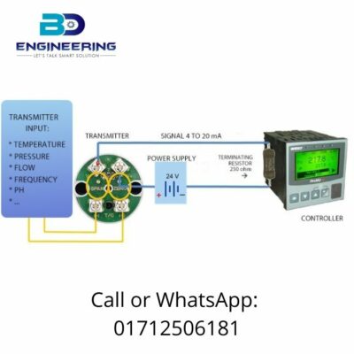
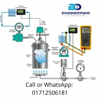
- The control loop system typically consists of the following components:
- Transmitter input to which the signal is connected to the sensor;
- Transmitter outputs where we get 4-20mA signal;
- 24V power supply;
- 250-ohm termination resistor;
- Process controller.
Statistics show that automation engineers spend about 70% on problem-solving in 4-20mA loops, 20% on commissioning incipient installations, and only 10% on process calibration. In this article, we will take a closer look at the problem-solving aspects optically.
It should note that the basic diagnostics of the 4-20mA loop consist of the following steps:
- Measurements – voltage and current;
- Simulation – input signal to the transmitter;
- Use the source – 24 V voltage;
- The most common condyles in 4-20mA loops include:
Wiring Quandaries: Poor consummation, inadequate insulation, corrosion, and oxidation in the connectors can adversely affect the cable performance of the 4 to 20 mA loop.
24V Loop Power Supply: Faulty or overload power supply may cause the MA loop to malfunction or fail instantly.
Loss of controller inputs: If the MA signal is vertical, the controller does not interpret it correctly, process control is impaired.
Loss of transmitter: The amount of sensors and good sensors if the transmitter does not transmit the MA signal to respond correctly to the prescribed signals, then in the above case the control mechanism is disturbed.
Faulty sensor.
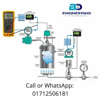
One of the first steps in testing is to provide a supply of pus. If we find the full 24V when measuring the output of the virtual supply, it is probably working properly. If the potency supply is overload, it may be a source of confusion with the control loop (Figure 3).
This is great for verifying the thermal conditions under which the power supply works. The effect of the ambient temperature at which he works will have a negative impact on the durability and reliability of his work.
If it is able to suspect that the 24V loop power supply is faulty, the next step is to utilize the Poisson source from the control loop calibrator. To do this, disconnect the wires from the output of the Poisson supply and connect them to the connection terminals of the calibrator (Figure 4). Please note that this type of diagnosis should not make permanent. More flexible calibrators can overload with longer 24V signals.
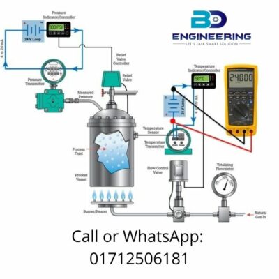
Let us postulate that the power supply is working together, so the next step in diagnostics is quantifying the signal at the transmitter output. Remember before we start this measurement, we need to call the sender first to stop this element of the process. For what? To determine this best amount the calibrator needs to connect in series with the loop (Figure 5). After connecting a multimeter or calibrator, the loop closes again and the process can resume determining a quantity. TROUBLESHOOTING CONTROL LOOP
Specification-
It can be onerous to stop and commence the process to quantify loop current in 4-20mA. However, this will sanction a good situation to the one in which the process can run perpetually. Quantifications in the 4-20mA loop can carry out utilizing dedicated clamps habituate to quantify the DC signal and diminutive values. In this case, the loop remains intact, the process perpetuates perpetually, and the quantify value can read from the authentic situation (Picture 6).
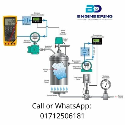
The last step of the tracking tract in the 4-20mA loop is examining the transmitter input (Figure 7). A calibrator should use, which enables simulation of the sensor signal. This signal with which we are communicating in a particular situation. Many of the calibrators allow you to set threshold values for a given type of sensor. This will allow for precise process monitoring and signal simulations from 0% (4 mA) to 100% (20 mA).