
Variable Frequency Drive, Let’s start from the basics to understand how they work?
VFD stands for Variable Frequency Drive. It uses for working an AC motor at variable speeds or letting it ramp up its speed to give them a smooth startup. We simply call it drives. It works by attaching the frequency of the motor to adjust the RPMs. For doing this, VFD will convert the voltage twice. First, it converts our three-phase AC to DC. This accomplishes with diodes. After it cleans the DC with a capacitor. Then this will convert the DC to AC.
Literally, VFD supplies to the motor what allows the VFD to adjust the frequency.
It in turn controls the speed of the motor. First, follow up at the diodes that convert the AC to DC. It’s like a check valve in a water system. This check valve looks like a diode with electricity, it only allows water to flow in one direction. And the capacitor acts like a water filter to keep everything clean and usable. The transistors act like valves. when need it turns the flow on and off. It allows the VFD to attach the frequency of the motor.
AC drives or variable speed drives and that’s because it uses for controlling the rotational speed of an AC motor, we find AC motors and VFDs use in industries but especially HVAC.
Let’s have a look, we can find them by using control our compressors speed in a refrigeration system. It allows us to closely match the cooling demand which will give outcome in necessary energy savings traditionally we would have to use a fixed speed compressor. so, these are simply turn on and turn off and that outcome in normal control and high currents.
Find out this is used to control things
such as pumps and fans in HVAC systems to allow us to unlock energy savings. and it improves performance and controls the Variable Frequency Drive unit involved in the motor electrical supply. The unit can differ in the frequency of the electricity being supplied to the motor drive. and by differing this it can control the rotational speed of the motor therefore it has frequency drive to understand how a VFD works.
Two types of electricity are there and the first one we’re going to look at is DC or direct current. This is the simplest type and we get this from batteries, solar panels, etc. We can think of DC as a river with a current of water flowing in just one direction with DC the electrons just flow in a single direction. Also, electron flow is included with these terms.
That is from the negative to the positive but you might be used to seeing conventional current which is from positive to negative electron flow. what’s actually occurring conventional was the original theory and this still uses widely today just be aware of the two theories and which one we’re using for electricity to flow. When we use the Scylla scope to look at the electrical waveform of DC, we get this flat line the maximum voltage in the positive region. We should complete the electric circuit and then always try to get back to its source.
Let’s get this-
We can think of this type like the tide of the sea which flows in and out between two maximum points our high tide and the low tide if we followed the copper wires back to the generator the wires are connected to some coils of wire that sit within the generator inside a basic generator we find a magnet at the center which is rotating the magnet has a north and the South Pole or they can think of it as a positive and negative half the electrons in the wire negatively charge and as it already knows magnets push or pull depending on the polarity as the magnets rotate past the coil.
Now, the positive and negative half-
they are going to push and pull the electrons within the copper coils and these will also move them through the connect copper wires the field of the magnet varies in intensity and we could see the magnetic field lines by spreading some iron filings over a magnet. The field of the magnet rotates past the coil and the coil experience a big change in the intensity of the magnetic field. After this, it would be from zero up to its maximum intensity, and this will decrease again back to zero when it sends the coil.
Then negative half comes in and pulls the electrons backward with the same change in intensity each full rotation of the magnet will produce this wave pattern known as the symbol of a sine wave, this repeatedly moves from zero up to its peak then back to zero then through the negative peak instead the voltage is not constant in this type of electricity.
After this finally back to zero again frequency refers to how many times, this AC sine wave could repeats per second in North America and other parts of the world. we can get 60-hertz electricity at the outlet. It means that the sine wave repeats 60 times per second and each and every wave has a positive. And negative half this means that the polarity will reverse 120 times per second in the rest of the world we mostly find 50 Hertz electricity. so the sine wave repeats 50 times per second and the current reverses 100 times per second.
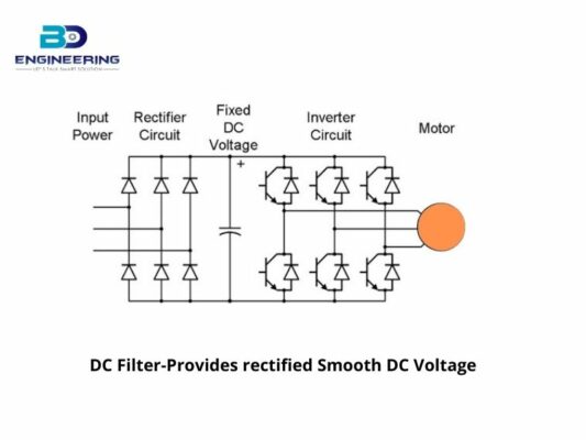
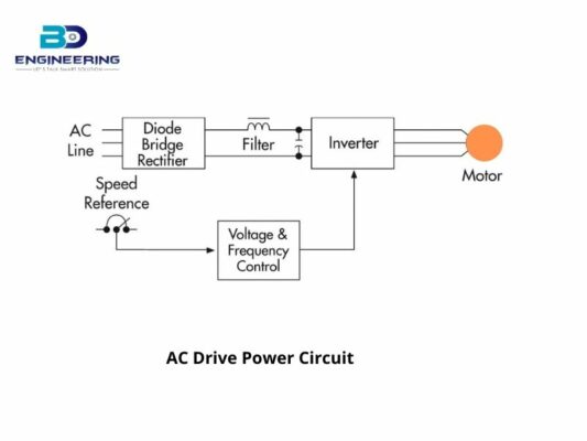
The block diagram is showing below that contains three different steps to follow the basic working principle of a Variable Frequency Drive:
VFD is showing its three different steps:
Rectifier- the capacitor and inductor for filtering that is contained by DC. The number of 3 is the DC-to-AC inverter. DC turns back to three-phase AC.
The VFD connects to the AC motor induction, it has enough capabilities of attachable speed and horsepower control that it looks like a DC drive. AC motor induction speed depends on motor poles and applied power. The poles of the motor can be increased or decreased, though it has limited usefulness. but the AC frequency is fixed at 50 Hz in China, the power electronics made it practical to indicate the frequency where the induction motor was working at different speeds.
Finally, let’s have a look at how it literally runs-
Commonly used in industry is to control the speed of a water pump in a water treatment facility. A water treatment plant randomly has a constant flow of water coming into the plant. the operator will need to slow down the supply if the water demand exiting the plant is lower than the supply entering the plant. It achieve by using a VFD on the AC motor. The VFD is attached when the operator can monitor water flow. On the other hand, the great thing about VFDs can control with a PLC.
It helps make a process like water treatment that much easier and more efficient. This setup can benefit from automation and it can use in any situation. Let’s look back at what we know now. Variable Frequency Drive stands for Variable Frequency Drive. It uses for controlling the speed of an AC motor. For a smooth startup, it uses for ramping up a motor, or it can also use to prevent a heavy load from straining the motor on startup. It accomplishes by adjusting the frequency delivered to the motor. A setup of an AC to DC converter, after that DC to AC converter. The VFDs are used throughout the industry.
A common thing is to regulate water flow entering a water treatment plant. And VFDs allow the operator to control the flow of the pump manually or automatically with a PLC.