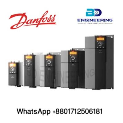
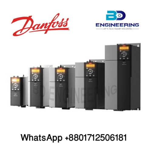
Danfoss inverter with on/off switch & potentiometer

More About Danfoss inverter
Hybrid Intelligent Inverter
An on-grid inverter’s main job is to convert DC power generated from the PV array into usable AC power. Hybrid inverters are special parts of this function and work with batteries to store excess power as well as that method. In the developing world, hybrid inverters are more of a necessity to compensate for weak or intermittent grids or a lack of grid electricity altogether.
Deye hybrid inverters include single-phase 3kW/3.6kW/5kW/8kW and three-phase 8kW/10kW/12kW, and all of them adopt a 48V battery. So, the solar energy storage system is safer and more reliable compared with a high voltage battery system.
several hardware elements and the Grid interactive inverter consists of it. The Grid is interactive and the electricity from the power plant inverter control and monitors the connection. In addition, it also controls the disconnection of excess power from the plants. at the peak time based on the demand of It ensures the dispatch of power. In case of the disconnection of the surplus power, the inverter prevents blackouts, by switching the supply of electricity to the systems that demand it most. the direct power supply from the main power plants and the grid-interactive inverter can also be used to switch to a Grid-to-Grid connection
Specification:
Mains supply (L1/L, L2, L3/N)
Supply voltage 200–240 V ±10%
voltage Supply 380–480 V ±10%
Supply frequency 50/60 Hz
mains phases 3.0% of rated supply voltage and Maximum imbalance temporary. True power factor ≥0.4 nominal at rated load
Displacement power factor near unity
Switching on input supply L1/L, L2, L3/N Maximum 2 times/minute
Environment according to EN60664-1 pollution degree 2
The unit is suitable for use on a circuit capable of delivering not more than 100000 RMS symmetrical Amperes, 240/480 V
maximum.
Motor output Output voltage 0–100% of supply voltage
Output frequency 0–200 Hz Switching on output Unlimited
Ramp times 0.05–3600 s Cable length and cross-section
Maximum motor cable length, shielded/armored 15 m (49 ft)
unshielded/unarmored 50 m (164 ft) Maximum motor cable length,
Connection to load sharing/brake (M1, M2, M3) 6.3 mm insulated Faston plugs
(M4, M5) 16 mm2 Maximum cross-section to load sharing/brake
/6 AWG Maximum cross-section to control terminals, rigid wire 1.5 mm2 16 AWG 2×0.75 mm2 Maximum cross-section to control terminals, flexible cable 1 mm2. Maximum cross-section to control terminals, cable with enclosed core 0.5 mm2. Minimum cross-section to control terminals 0.25 mm2.

