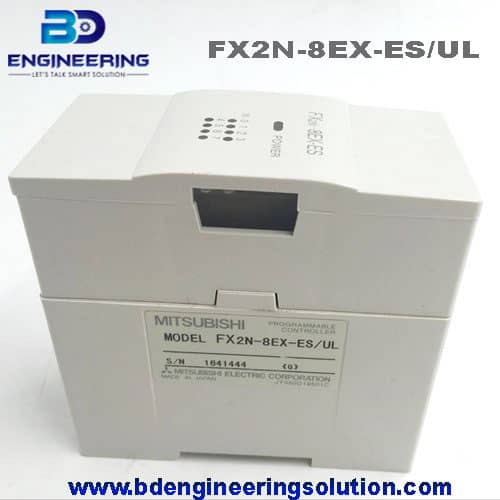
FX2N-8EX-ES/UL RS-232 5mA Mitsubishi PLC Expansion Module 8 Digital I/O. The FX2N-8EX-ES/UL is an expansion module for Mitsubishi Electric’s FX Series PLCs, specifically designed to provide additional digital input and output (I/O) capabilities. This module features 8 digital input/output channels and utilizes RS-232 communication for connection with the PLC. Here’s a detailed guide on this expansion module and its usage:
FX2N-8EX-ES/UL Module Overview:
- Digital Inputs and Outputs:
- The FX2N-8EX-ES/UL module provides a total of 8 points:
- 8 digital inputs (24V DC sink/source selectable)
- 8 digital outputs (relay type, 2A per point)
- The FX2N-8EX-ES/UL module provides a total of 8 points:
- Communication Interface:
- The module communicates with the PLC via an RS-232 interface.
- RS-232 is used for serial communication, allowing the PLC to control and monitor the module’s I/O points.
- Compatibility:
- Compatible with Mitsubishi Electric’s FX3G, FX3U, and FX3UC Series PLCs.
- Ensure compatibility with your specific PLC model and system requirements.
Installation and Setup:
- Physical Installation:
- Power off the PLC and any connected devices.
- Insert the FX2N-8EX-ES/UL module into an available slot in the PLC base unit.
- Securely mount the module using the provided mounting brackets.
- Wiring Connections:
- Connect external devices (sensors, switches, actuators, etc.) to the digital input and output terminals on the FX2N-8EX-ES/UL module.
- Ensure correct polarity and voltage levels according to the module’s specifications.
- RS-232 Connection:
- Use an appropriate RS-232 communication cable to connect the FX2N-8EX-ES/UL module to the RS-232 port on the PLC.
- Ensure that the cable is securely connected and properly configured.
Programming and Configuration:
- PLC Configuration:
- Use Mitsubishi’s GX Works2 or GX Developer software to configure the PLC program.
- Add the FX2N-8EX-ES/UL module to the PLC configuration.
- Define the digital input and output points associated with the module in the PLC program.
- Programming I/O Points:
- Write ladder logic or program instructions to read from or control the digital input and output points connected to the FX2N-8EX-ES/UL module.
- Map the input and output addresses in the PLC program to correspond with the physical wiring of external devices.
Testing and Operation:
- Testing Inputs:
- Apply signals (e.g., from switches or sensors) to the digital input channels.
- Monitor the PLC program to ensure that the input signals are correctly detected and processed.
- Testing Outputs:
- Activate output commands in the PLC program to control the digital output channels.
- Verify that connected devices (e.g., relays, indicators) respond as expected to output commands.
Safety Precautions:
- Ensure that all wiring connections adhere to safety standards and local regulations.
- Power off the PLC and equipment before installing or removing the FX2N-8EX-ES/UL module or making any wiring adjustments.
- Double-check the compatibility of the FX2N-8EX-ES/UL module with your specific PLC model to avoid compatibility issues.
By following these steps and guidelines, you should be able to effectively integrate and utilize the FX2N-8EX-ES/UL expansion module with your Mitsubishi FX Series PLC system, expanding its digital I/O capabilities and enabling control and monitoring of external devices through RS-232 communication. Refer to the module’s user manual and PLC programming software documentation for detailed instructions and troubleshooting assistance.