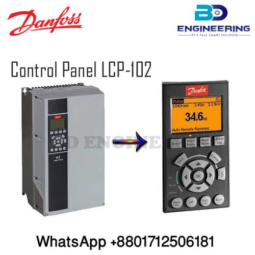
Danfoss VFD Inverter Control Panel LCP 102 for Automation Drive in BD. The LCP control panel operating the VLT Drive which is a setup parameter as per user requirements also shows frequency in the Display.
The Programming Guide for VLT® AutomationDrive FC 301/FC-302, LCP FC-102/FC-101 and Software versions, and control card MK 7.62 48.2X and Software version, control card. Also, Danfoss VFD Inverter Control Panel LCP 102 for Automation Drive in BD
How to set up the Program in the VFD Inverter of Danfoss Drive which is for Automation Drive FC-301 FC-302?
- Part No: 130B1107
- High Over Loaded
- Heavy Duty
- Special Breaking System
- LCP-Display Controlling
- Analog inputs available
- Digital inputs Available in the Drive for Switching
- The analog inputs are used for controlling various
- Functions of the frequency converter.
- There are 2 types of analog inputs:
- Current input, 0–20 mA, and 4–20 mA
- Voltage input, -10 V DC to +10 V DC.
The Brake resistor:
The brake resistor is a module capable of absorbing the brake power generated in regenerative braking. This regenerative brake power increases the DC-link voltage and a brake chopper ensures that the power transmit to the brake resistor.
The CT characteristics:
Constant torque characteristics are available for all applications such as conveyor belts, displacement pumps, and cranes.
LCP-Display for VLT Drive:
The local control panel makes up a consummate interface for the control and programming of the frequency converter. The control panel is detachable and can be installed up to 3 m (10 ft) from the frequency converter, that is, in a front panel with the installation kit option.
