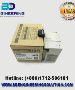
The FX3U-16MR/ES is a part of Mitsubishi’s FX3U series of programmable logic controllers (PLCs). These PLCs are widely used in industrial automation for their flexibility, reliability, and extensive range of features. Here’s a detailed overview of the FX3U-16MR/ES model:
Key Features of FX3U-16MR/ES
- Integrated I/O:
- Digital Inputs: The FX3U-16MR/ES includes 8 digital input points.
- Relay Outputs: It provides 8 relay output points, suitable for controlling various types of loads.
- Processing Speed:
- The FX3U series offers fast processing speeds, making them suitable for high-speed applications.
- Expandable:
- The FX3U series can be expanded with additional I/O modules, communication modules, and special function modules, allowing for customization and scalability based on application needs.
- Memory:
- The FX3U series typically features a large program memory to accommodate complex programs and data.
- Communication Options:
- The FX3U PLCs support a variety of communication protocols and modules, including RS-232, RS-485, Ethernet, and more. This allows integration with various devices and systems within an industrial environment.
- Programming:
- Mitsubishi PLCs, including the FX3U series, can be programmed using Mitsubishi’s GX Developer or GX Works software. These programming environments offer powerful tools for creating, debugging, and managing PLC programs.
- Power Supply:
- The FX3U-16MR/ES model operates on a 100-240V AC power supply, making it suitable for a wide range of industrial environments.
- Robustness:
- Mitsubishi PLCs are known for their durability and reliability, capable of operating in harsh industrial conditions.
Typical Applications
The FX3U-16MR/ES can be used in various industrial applications, including:
- Manufacturing automation
- Process control
- Material handling systems
- Packaging machinery
- Building automation
Installation and Wiring
When installing and wiring the FX3U-16MR/ES, it’s crucial to follow the guidelines provided in the Mitsubishi
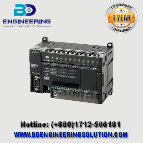
The OMRON CP1E-N14DT-D is a compact PLC from OMRON’s CP1E series. This model features 8 DC inputs and 6 transistor (NPN) outputs. It’s designed for small-scale automation tasks with basic control requirements.
Here’s an overview of the CP1E-N14DT-D and a basic example of how to create a simple ladder logic program using OMRON’s programming software, typically CX-Programmer.
Key Features of CP1E-N14DT-D
- Integrated I/O:
- Digital Inputs: 8 inputs (24V DC)
- Transistor Outputs (NPN): 6 outputs (24V DC, sink type)
- Processing Speed:
- Provides adequate speed for small to medium automation tasks.
- Programming:
- Programmable using OMRON’s CX-Programmer, which offers a range of programming tools for ladder logic, function block, and structured text.
- Communication Options:
- Built-in RS-232C port and options for additional communication modules.
- Power Supply:
- Requires a 24V DC power supply.
- Compact and Robust:
- Designed for easy installation in small spaces with robust performance.
Basic Ladder Logic Program Example
Step-by-Step Guide:
- Install CX-Programmer:
- Ensure you have a CX-Programmer installed on your computer.
- Create a New Project:
- Open CX-Programmer and create a new project.
- Select the CP1E-N14DT-D PLC model.
- Create a Ladder Logic Program:
- In the project workspace, create a new ladder diagram.
- Insert Input and Output Instructions:
- Add a contact (normally open) for input 0.00 (IN0).
- Add a coil for output 100.00 (OUT0).
- Connect the Contact and Coil:
- Connect the contact and coil in a single rung.
- Download the Program:
- Connect your computer to the CP1E-N14DT-D PLC using the appropriate cable (typically a USB or RS-232C cable).
- Download the program to the PLC.
- Monitor and Test:
- Use the monitoring tools in CX-Programmer to test and ensure the logic works as intended.
- Activate the input (IN0) and check if the output (OUT0) turns on.
Summary
The OMRON CP1E-N14DT-D PLC is suitable for small automation tasks with its compact design and integrated I/O. Using CX-Programmer, you can create and download ladder logic programs to control outputs based on input conditions. The example provided is a basic starting point, and you can expand your program to include more complex logic as needed.